(this discussion is continued in Oscillators' basics)
In the beginning, there was the original beat. The tightly controlled frequency of a precisely cut quartz crystal that sets the rythm of the rest of the circuit.
Getting this crystal is easy today, getting it to oscillate properly is a totally different thing. Making it work with a discrete complementary MOSFET driver is yet another story.
Half a century ago, our predecessors would use a pair of NPN to run a watch out of a 8192Hz crystal and a small coin battery:
(source: http://ethw.org/First-Hand:The_First_Quartz_Wrist_Watch)
I haven't seen this topology used since then, people use these circuits instead today:

Complementary Mosfet Pair
(see http://www.bowdenshobbycircuits.info/page11.htm)

Oh wait, the 2N2904 is a PNP, not NPN type.. wth ?
Complementary pairs of MOSFETs can be disabled by connecting them as standard CMOS inverters (i.e., gate-to-gate and source-to-source) and tying their inputs to ground, as shown in Figure 7. Individual MOSFETs can be disabled by tying their source to their substrate and leaving the drain open circuit. Diodes' 8V to 29V Complementary MOSFETs are designed to minimize the on-state resistance (RDS (on)) and yet maintain superior switching performance. The MOSFET is used in digital complementary metal–oxide–semiconductor logic, which uses p- and n-channel MOSFETs as building blocks. Overheating is a major concern in integrated circuits since ever more transistors are packed into ever smaller chips. Complementary MOSFET symbol in Multisim(Electronics Workbench) Ask Question Asked 6 years, 1 month ago. Active 6 years, 1 month ago. Viewed 1k times 1 $begingroup$ It is just me or symbol for complementary mosfet pair in NI Multisim is wrong? And actually not just the symbol, but the function itself - it doesn't work as it is supposed to(or.
I have already explored discrete Xtal oscillator circuits at https://hackaday.io/project/8121-discrete-yasep/log/26870-clock-generation-circuit but 32KHz is a different and more sensitive domain.
For our purpose, the left circuit (similar to the higher frequency one) is not accepted because it uses an integrated circuit. That would be too easy. On the right, it uses a single bipolar transistor (how 70's !) and the 68K pull-up wastes energy. Bluestacks whatsapp mac download. I want a low-power full CMOS design. Just because.
Copyclip mac download. In theory, the 4069 inverter gate should be easily replaced by a pair of complementary MOSFET. This raises the question of the influence of the combined gate capacitances.
Not shown is the series resistor that K.C. suggested in the comments, I'll have to try it before I commit to the design. For now I'm trying to KISS.

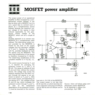
Complementary Mosfet Driver
Also missing is a LC filter between the P-MOSFET and VCC.
